We chose a rigid titanium adjustable cantilever frame. I will write more about this later. Here are the general frame specs:
TiLite ZRA Frame Finish: Natural Titanium Satin
Tubing Diameter: 1.25″ / 31.75 mm
Titanium strength
More to come …
Titanium vibration dampening
More to come …
Titanium appearance
We wanted a satin finish titanium so we could buff out scratches and dings, which happen a lot when you have hemispatial neglect which affects the visual field on one side.
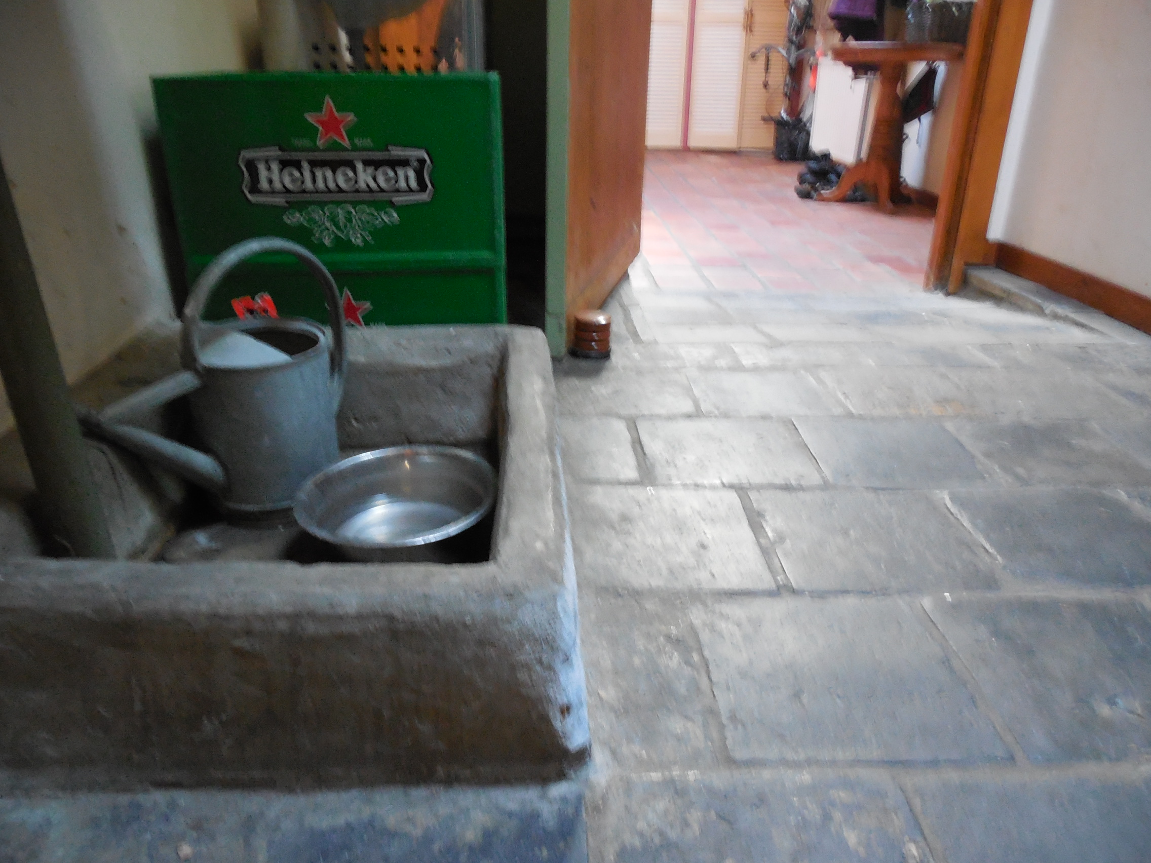
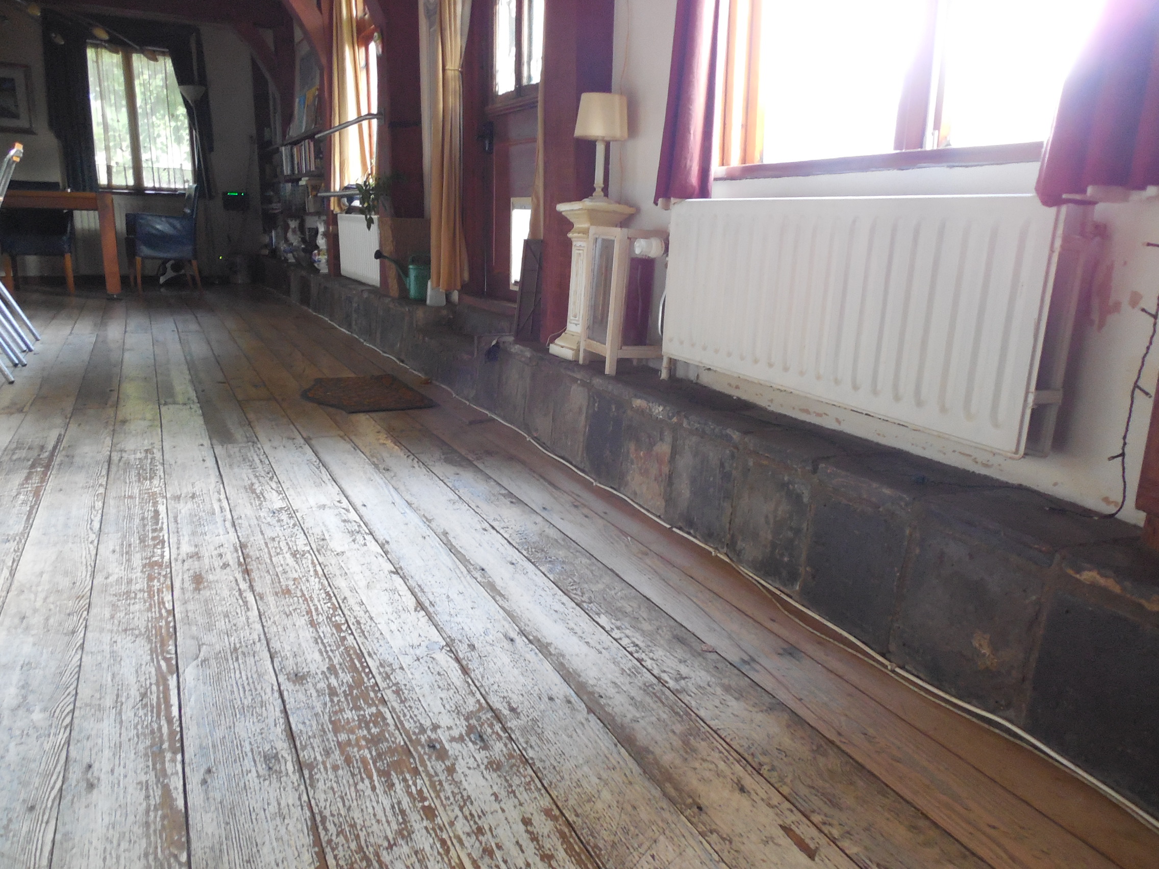
We live in a 450 year old house that has some stone and cement “features” that are bashed into constantly, due to a reduced visual field. Outside it is even worse with curbs, posts, etc. Any annodized aluminium surfaces look like they have been through a crash test, e.g., handrims.
Color Anodize Package: Black
This is the standard no-charge, and we decided to carry it through also with the wheel hubs and as many other components as possible.
Rear Seat Width: 16”
Based on measurements and is correct.
Front Seat Width (Seat Taper): No Taper 13.5″
Based on needing room for flip-up footrests to do foot propulsion.
Seat Depth: 18″ + 1″ for 19” in total
Based on measurements and is correct. The extra 1″ custom length makes the chair very stable, yet the overall chair length is still not too long for being able to get around and for maneuverability.
Front Seat Height: 18.5″
Based on measurements and needing to make compromises for foot propulsion, which requires your feet closer to the ground. We almost choose 19″, which would have been better if using footrests, but is too high for foot propulsion. With a fairly high 3.8″ thick Varilite Evolution PSV seat cushion and a solid seat base, we could have probably gone with 18″, but we would have had more problems with the Rear Seat Height and would be at a bad angle when sitting in the chair with both feet on the footplates. He uses the cushion to add or remove air to adjust for height, dependent on the situation. I think we got the about as good as possible give all of the variables at play.
Rear Seat Height: 17″
Based on measurements for good arm propulsion and comfort, but we need to make compromises for foot propulsion because that is not easy with too much dump. I think we got the about as good as possible give all of the variables at play.
Front Frame Angle: 85°
This angle has worked out well. It keeps the overall chair length not to long, yet is still comfortable for having feet in a natural position.
Seat to Footrest: 16.5″
Based on measurements for good foot propulsion and also comfort when the footrests are used. I think we got the about as good as possible give all of the variables at play.
Seat Back Angle: 92°
This angle has worked out well. Having an ADI solid back allows some adjustment of the angle for comfort.
Axel Position / Center of Gravity (CoG): 3”
The relationship between an object’s center of gravity and its fulcrum determines when an object tips over. By adjusting the position of the camber tube, you adjust the rear fulcrum of the chair. Changing the rear fulcrum involves moving the rear wheels forward and backward on the chair frame. When the fulcrum location or the user’s position is changed, the center point of the combined chair and user weight (true CoG) moves forward or backward on the chair frame in an inverse relation to the rear wheels and casters.
The weight of the rider as well as distribution of that weight (mass) impacts how the chair performs in different situations. The human body’s center of mass/gravity is always changing when any part of the user is moving (e.g., arm, head, trunk).
When going up a slope the upper body is off-center backwards (i.e., more aft in relation to the fulcrum). The more the weight is distributed forward (aka user leans forward shifting their CoG forward toward the original relationship to its fulcrum), the less likely that the person will tip over backward.
When going down a slope the upper body is off-center forwards. The more the weight is distributed backward (aka user leans backward again shifting the CoG toward the original CoG-to-fulcrum relationship), the less likely that the person will tip over forward (aka “endo”).
The axle position is measured as the horizontal distance (perpendicular to the force of gravity) from the center of axle tube (middle of wheel) to the front of the back post. This relationship determines the fulcrum location around which the (true) CoG of the user+chair rotates/tips backward. A good rule for new users is to align the axle directly under users hips in proper seated position.
Fulcrum location on a wheelchair tipping backward is the point where the rear tires touch the ground; Fulcrum location for a wheelchair tipping forward (endo) is where the casters touch the ground. (“Endo” is short for end over end.) The fulcrum is the center point of a vertical circle the radius of which is determined by the as-the-crow-flies distance between the fulcrum and the CoG.
Axel Forward (backward tipping)
Having the center of gravity too far backward causes backward tipping. The more you move the rear axel forward, the more likely your chair will tip over backward. When moving the axel forward on the chair frame the center of gravity is moving backwards in relation to the position of the wheels and casters which takes more and more weight off the casters allowing them to roll and swivel more easily.
When going up a slope a chair with the back wheel placed in the forward position is more likely to tip backwards because the center of balance is forward. The chair is more likely to tip over backwards if the user is self-propelling the chair vigorously or climbing hills and ramps. The further back the center of gravity the more backward tippier the wheelchair is.
Axel Backward (caster loading)
Having the center of gravity too far forward causes caster loading. By moving the axel backward on the frame more weight is loaded onto the front casters because the weight is centered between the casters and rear wheels. As the axels are adjusted further backwards the center of gravity of the wheelchair moves forward and the amount weight loaded on the casters increases.
When too much weight is loaded on the casters they will tend to roll less easily and make their swivelling more difficult due to the stresses put on the bearings. This is especially an issue on soft terrains such as lawns because the casters will not normally roll or swivel easily anyway.
Axle Position and Propulsion
The more forward position of the rear wheel improves pushrim biomechanics, shoulder joint forces, push frequency and stroke angle.
The axle position of up and forward results in an increase in speed and acceleration with a higher stroke frequency and a decreased shoulder ROM. The axle position of down and backward results in in a lower speed and acceleration with a lower stroke frequency and an increased shoulder ROM.
The optimal position for efficient propulsion is:
- The shoulder position is 2” to 3″ posterior (behind) the rear axle.
- The rear axle is in line with the greater trochanter.
- The push rim is 2” below the elbow (arms at sides).
- The elbows are flexed 100-120° with hands on rims.
Propulsion and Use
- Only able to use one arm/hand and on leg/foot to propel due to hemiparesis.
- Trunk control is very good on the propelling side, but limited on the affected side.
- Arm and hand strength and dexterity are very good on the propelling side.
- Tends to slouch forward, especially when tired.
- Does not do wheelies and only self propels indoors and on level services.
- Has anti-tips set quite low to the ground.
- Does not use the best biomechanics when pushing the chair. Tends to start too far forward and not at the top of the rim, but is trying to improve on this.
-
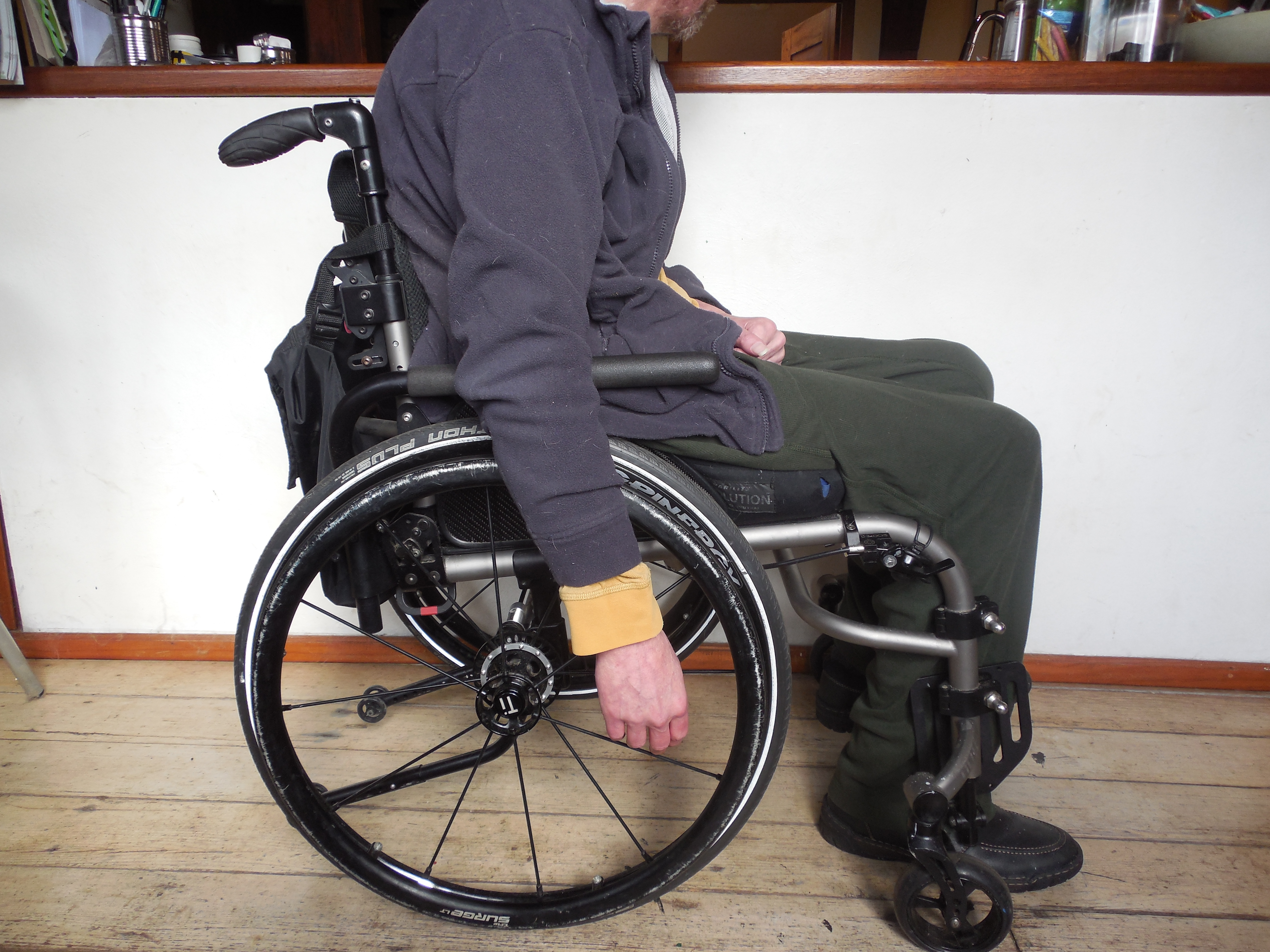
- Position at rest relaxed
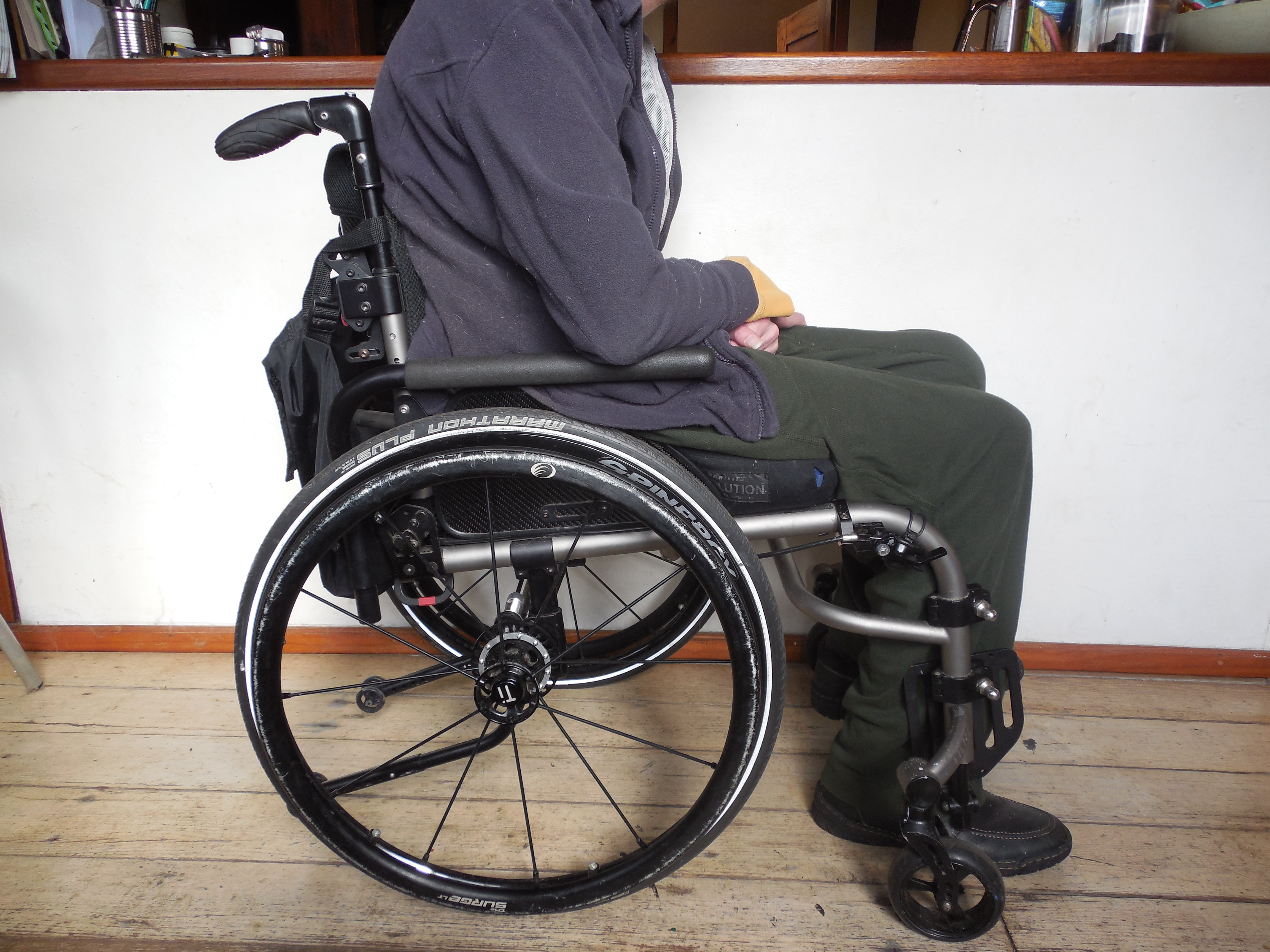
-

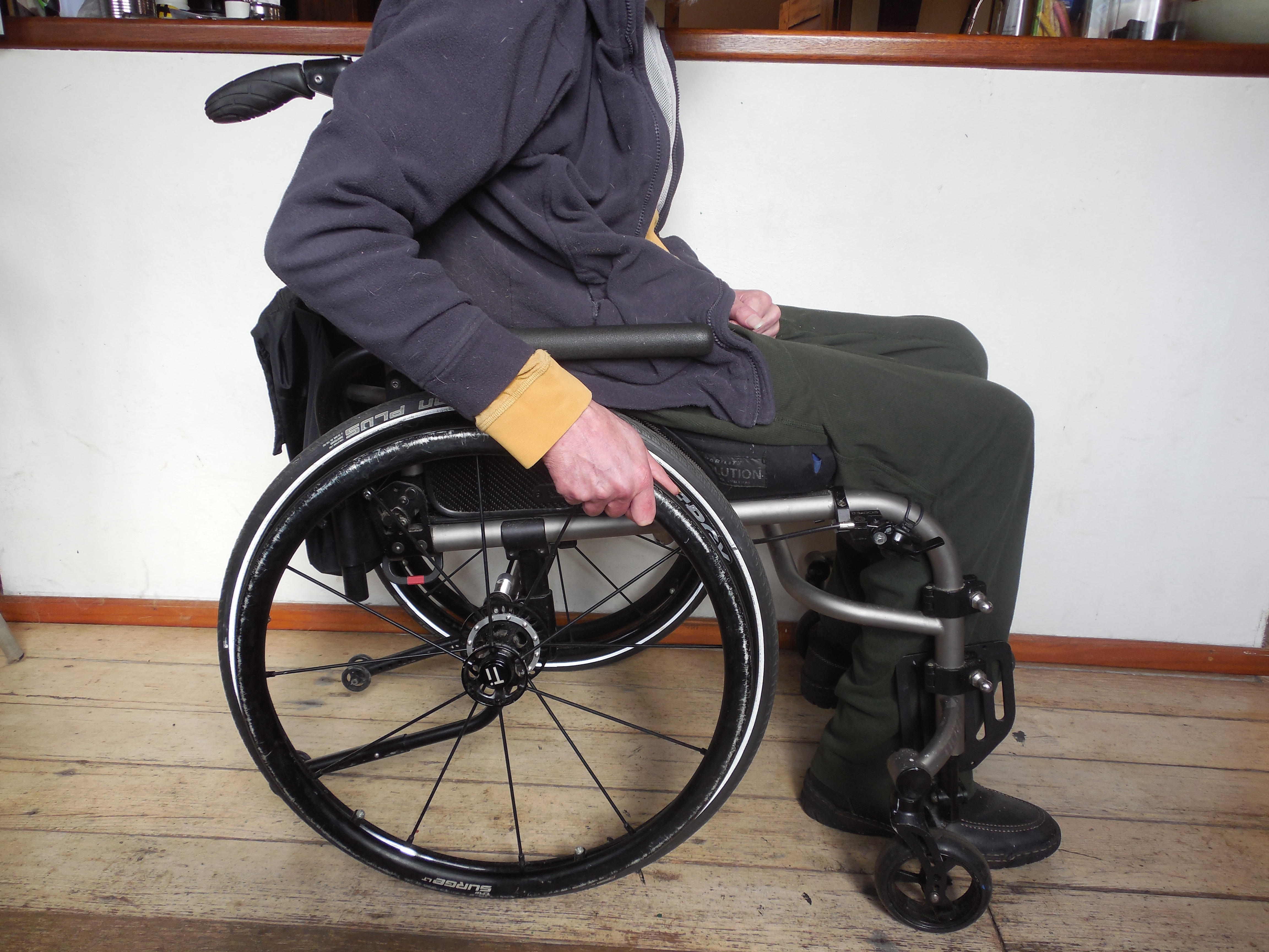
- Position at rest relaxed with arm extended
-
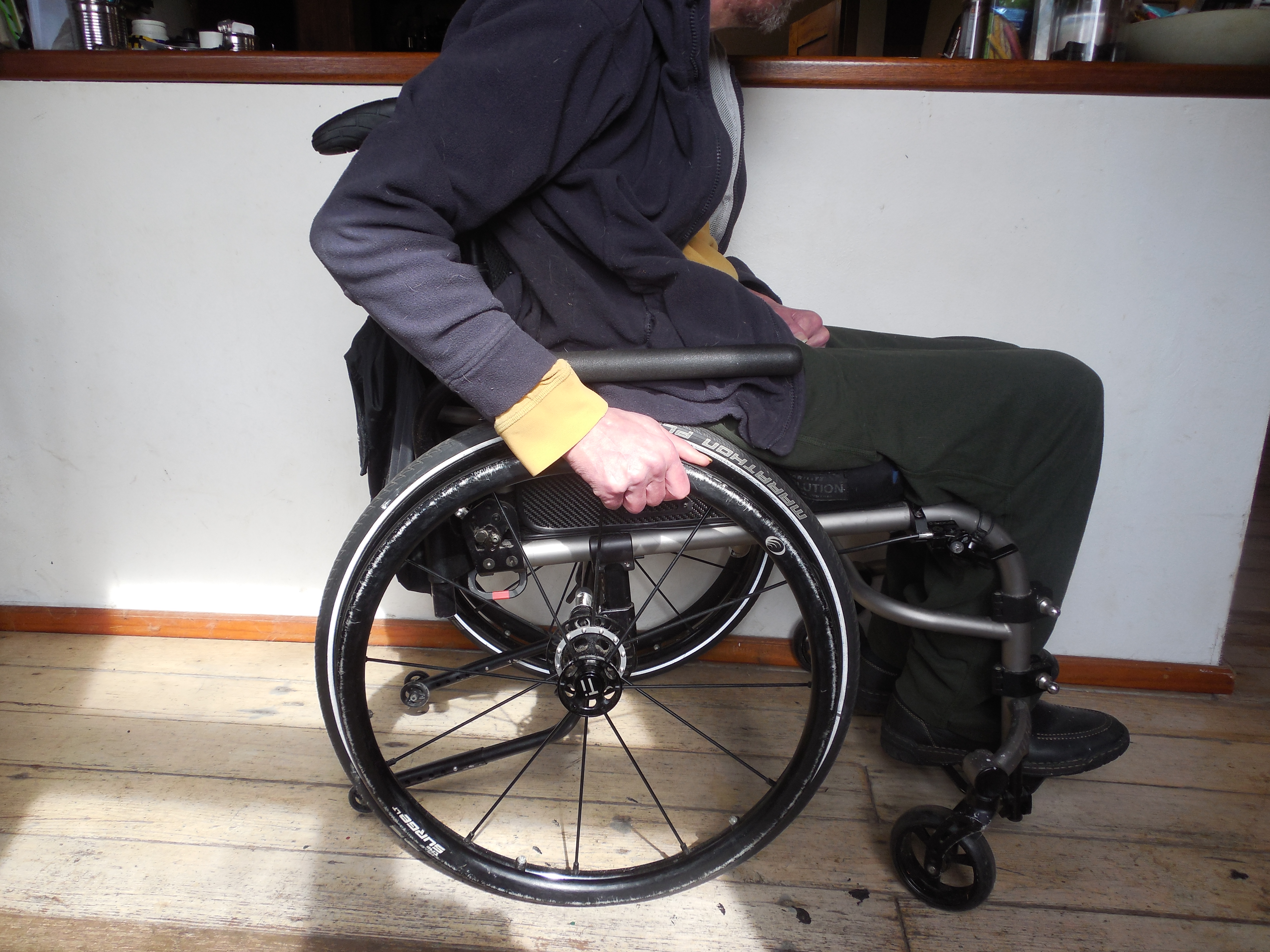
- Position propelling currently (not optimal)
-
- Position propelling proposed (optimal)
-

- CAD – Q102732_D Side
Summary of Axle Position
Forward Axle relative to CoG
Propulsion efficiency
Rolling Resistance
|
Backward Axle relative to CoG
Propulsion efficiency
Rolling Resistance
|
Adjusting the Axle Position
Whenever you adjust the position of the camber tube, either to adjust the rear seat height or the center of gravity, it may be necessary to adjust the toe-in/toe out of the rear wheels and to square the front casters to the floor.
Rear Wheel Spacing: 1”
I’m glad we went with 1″ spacing, rather than with anything less. It allows enough room for sideguards, but is not so wide as to make the chair too wide for being able to get around and for maneuverability.
Camber: 2°
This camber has worked out well.It is enough for a little bit more stability, without widening the chair too much to get through doorways. It also does not affect the D’s Locks too much, which 4-6 degree of camber might have made more of the holes unreachable.
Advantages to More Camber
|
Disadvantages to Less Camber
|
Camber Tube Type: Titanium
I’m glad we got Titanium, because of the extra strength seems like a good idea for the ZX-1 power add-on. We also ordered Additional Spacers to Increase Rear Wheel Spacing, but so far they have not been needed.