For other All-Terrain Third Wheels on the market and why we did not choose them, see All-Terrain Third Wheels. Many of the points are also covered on a thread Modified All-Terrain Third Wheel on CareCure.
Why a Modified All-Terrain Third Wheel
We are doing this project because there are no viable options on the market that will work. The primary use is for the when my husband uses his ZX-1 power add-on, which is mounted on the camber tube, with a TiLite ZRA wheelchair with individual flip-up footrests. Products mounted on the camber tube or on the on the footplate will not work. See All-Terrain Third Wheel Options on our website for an overview of products we have looked into.
We decided to use the Rio Mobility attachment because we also have a full Firefly that he will be using at other times, and we want to use the same mounting brackets and pawns. There is not enough room on the front frame for any other attachments.
Just as a bit of history, when we started this project we were in a rush to order the parts, because we had a deadline with the government for receiving funding. It was all done as a “leap of faith” in the hope that it will work, with the help of Rio Mobility in being flexible to let us order only the parts we think were needed.
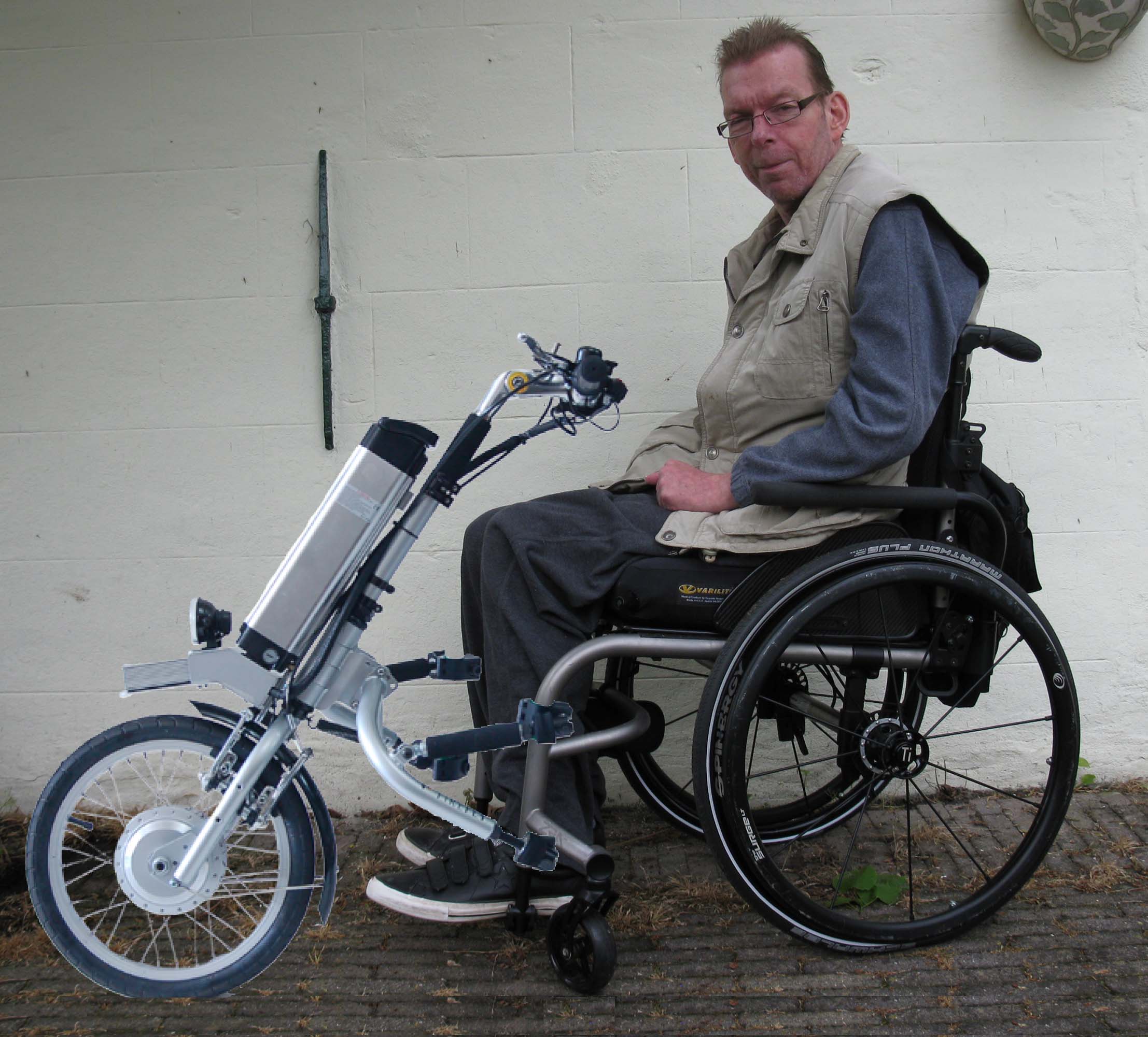
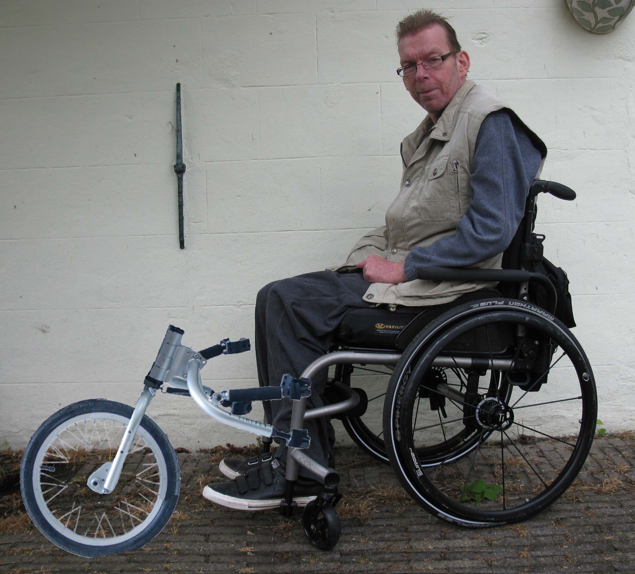
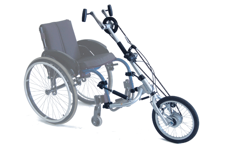
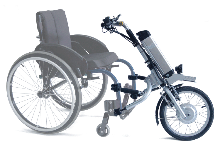
Here are some very rough Photoshopped images (angles are wrong) of Rob with the Rio Mobility attachment and a rough mock-up as a all-terrain third wheel. Of course, all the details will need to be figured out, but this is to give a rough idea of what we are thinking about.
Parts we bought from Rio Mobility
What we ordered from Rio Mobility were the attachment assembly, fork, attachment brackets and pawns (including screw and washers). We ordered the 1″ attachment brackets to use with a TiLite 2GX folding chair, because we already have the 1.25″ brackets for a TiLite ZRA2 that we ordered with the full Firefly.
It looks to me like you sent us a Dragonfly attachment (as printed on the wings) and fork, and possibly an older version, because it looks different than what is on the website now. It is causing some problems because the plan is to be able to use the same brackets mounted at the same position as for the full Firefly. Here are the differences:
- The Upper Arms that twist into the Threaded Rod are different (Dragonfly = 10 cm, Firefly = 13 cm). This may affect the placement of the upper Pawns, that we want to be the same for both the Firefly and the Third Wheel, because we will not be able to extend them as far.
- The forks are different, (Dragonfly = vertical, Firefly = offset ~3 cm) that could possibly allow for a negative rake. It also does not appear as strong on the Dragonfly.
- There are differences in the Wing Plate (Dragonfly = 5 holes, Firefly = 4 holes) and the Steering Plate (Dragonfly = 2 holes, Firefly = 3 holes).
- There are differences in the sockets and the Firefly seems easier to attach, and possibly stronger.
- The attachment is a smaller circumference (Dragonfly = 8 cm, Firefly = 9 cm).
- The Firefly has neoprene covers, which make it more comfortable.
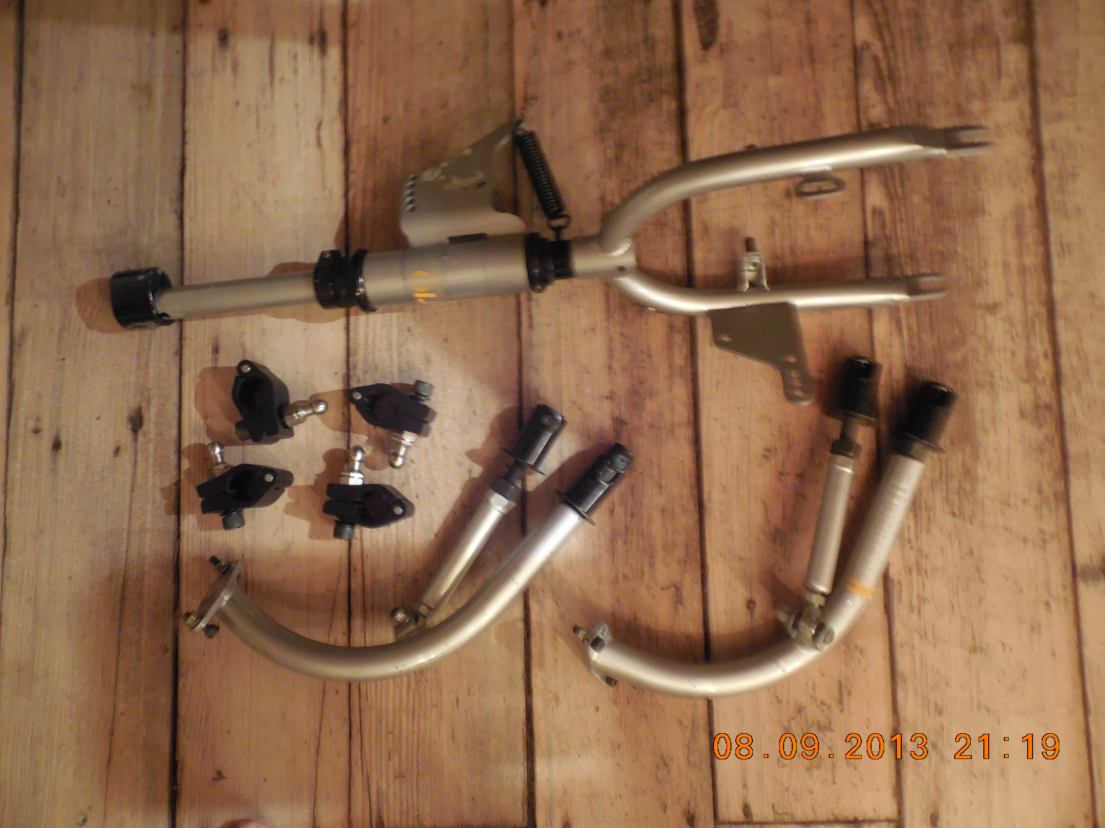
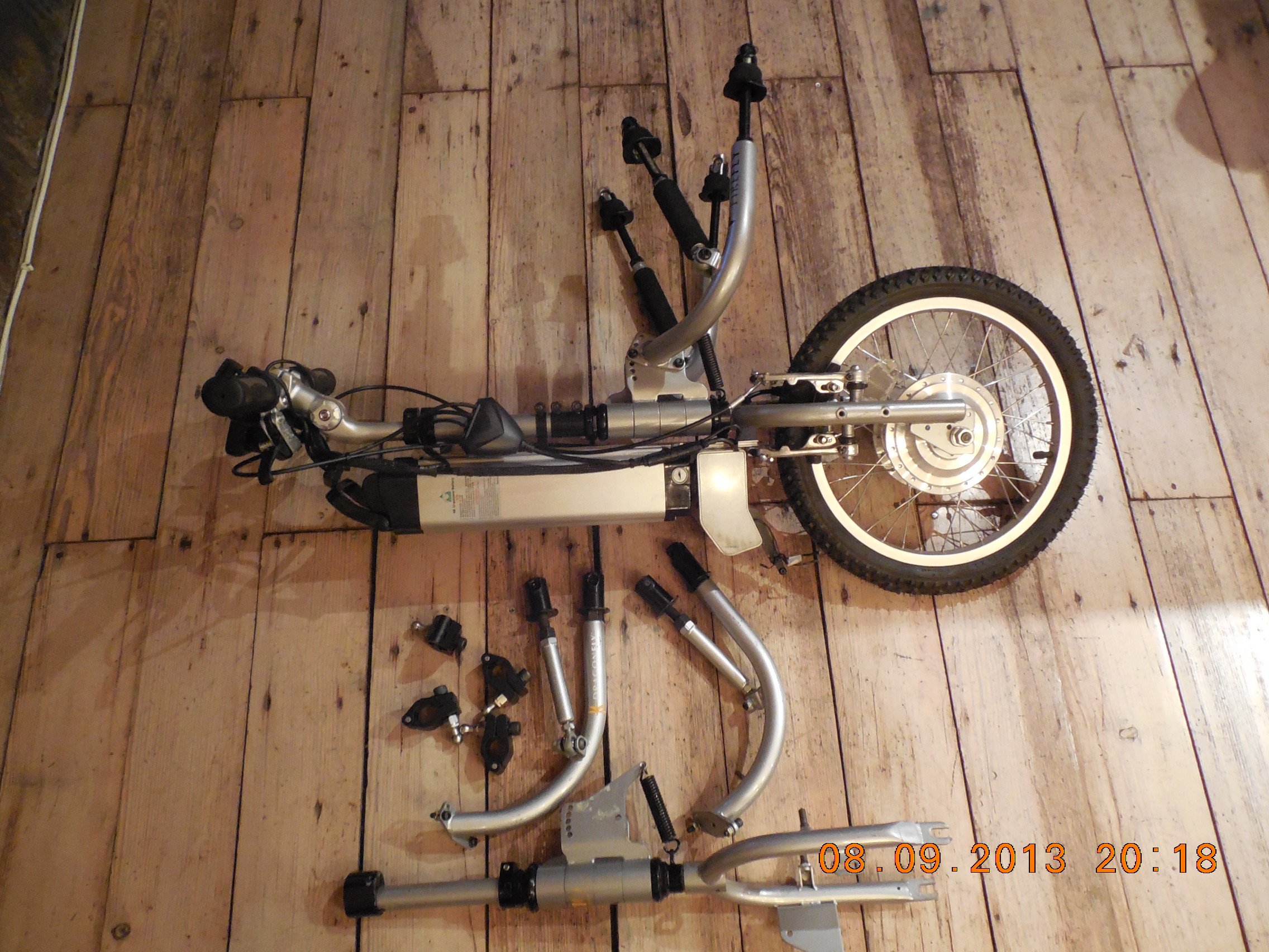
Here are pictures of the parts we received with the Dragonfly attachment and fork, along with a comparison with our current Firefly attachment,
-
- Dragonfly attachment and fork
-
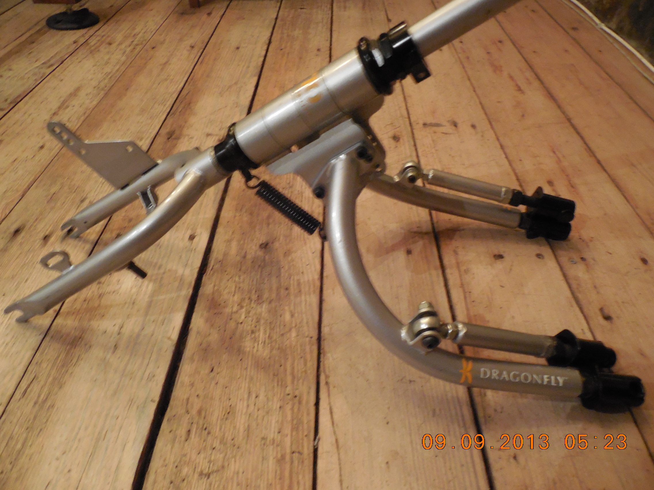
- Dragonfly attachment and fork loosely assembled
-
- Firefly vs. Dragon fly attachment and forks.
-
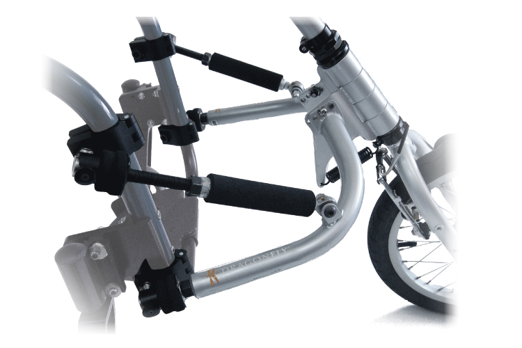
- Dragonfly attachment (from website)
-
- Dragonfly (from website)
-
- Firefly (from website)
Parts we bought seperately
We got a used 12″ kids bike and a used 16″ wheel and fork from a recumbant bike, along with a longer 6.5″ axel (165 mm x 10 mm diameter) to test with the wider Dragonfly fork.
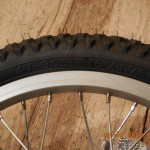
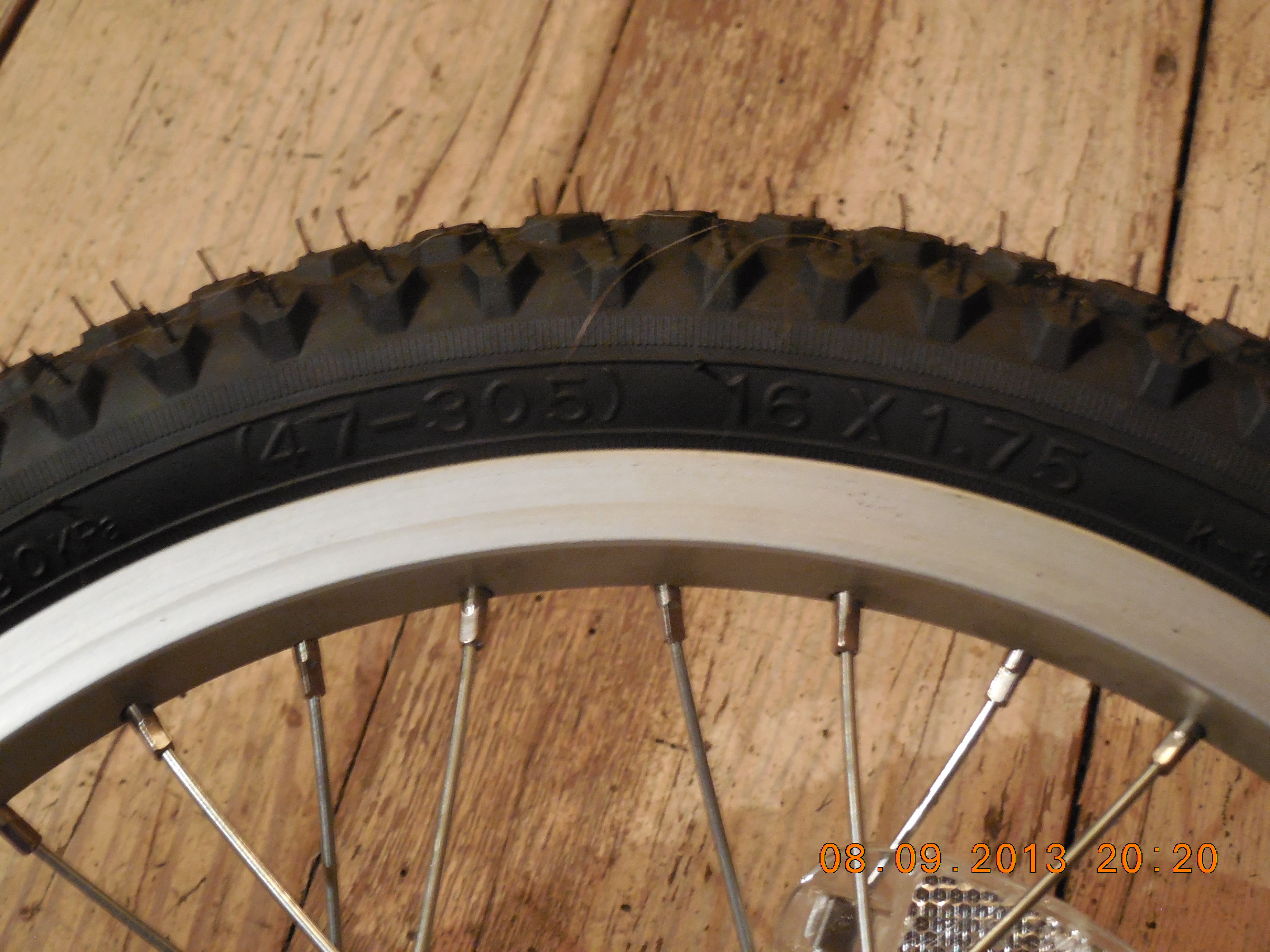
Note: According to the Firefly Users Manual, the current tire is 16” x 1½” (40 x 305) Kenda Quest all-tread tire. I think this must have changed and is now a 16” x 1¾” (47 x 305) Kenda tire (not sure which model). I think for now we will buy cheap 12″ and 16″ wheels and forks to prototype with, and see where it goes from there..
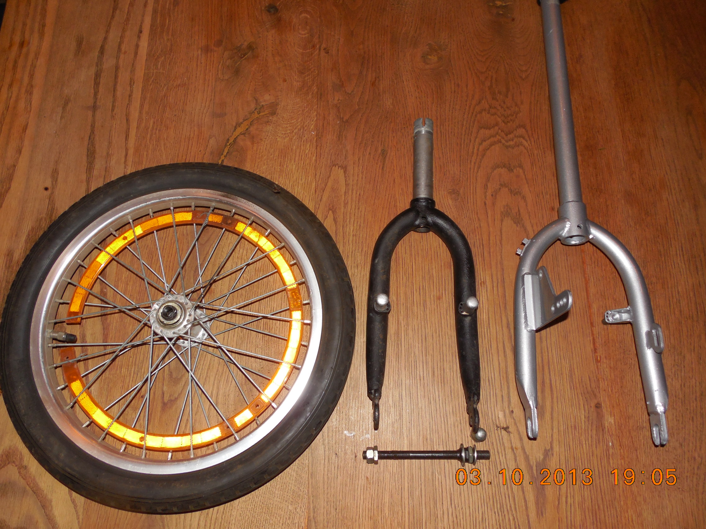
Here are pictures of the 12″ and 16″ wheels and forks we bought seperately (6.5″ axle not shown).
-
- 12″ wheel and 16″ and 12″ forks
-
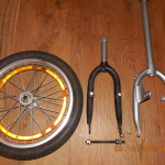
- 16 ” wheel and forks
-
- 16 ” wheel and fork
-
- Firefly wheel
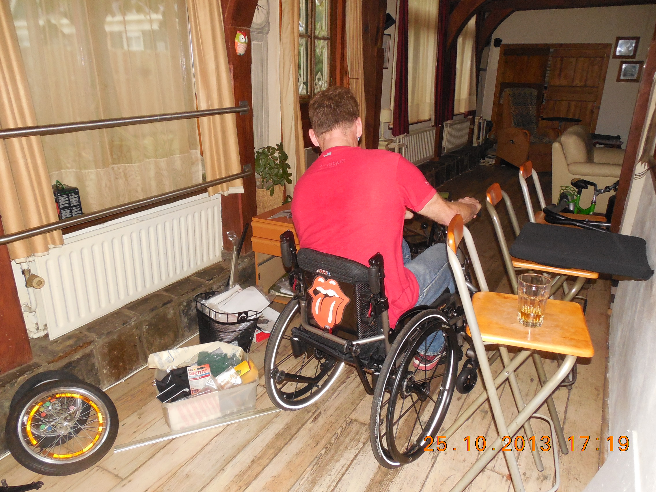
Testing Step 1 (October 2013)
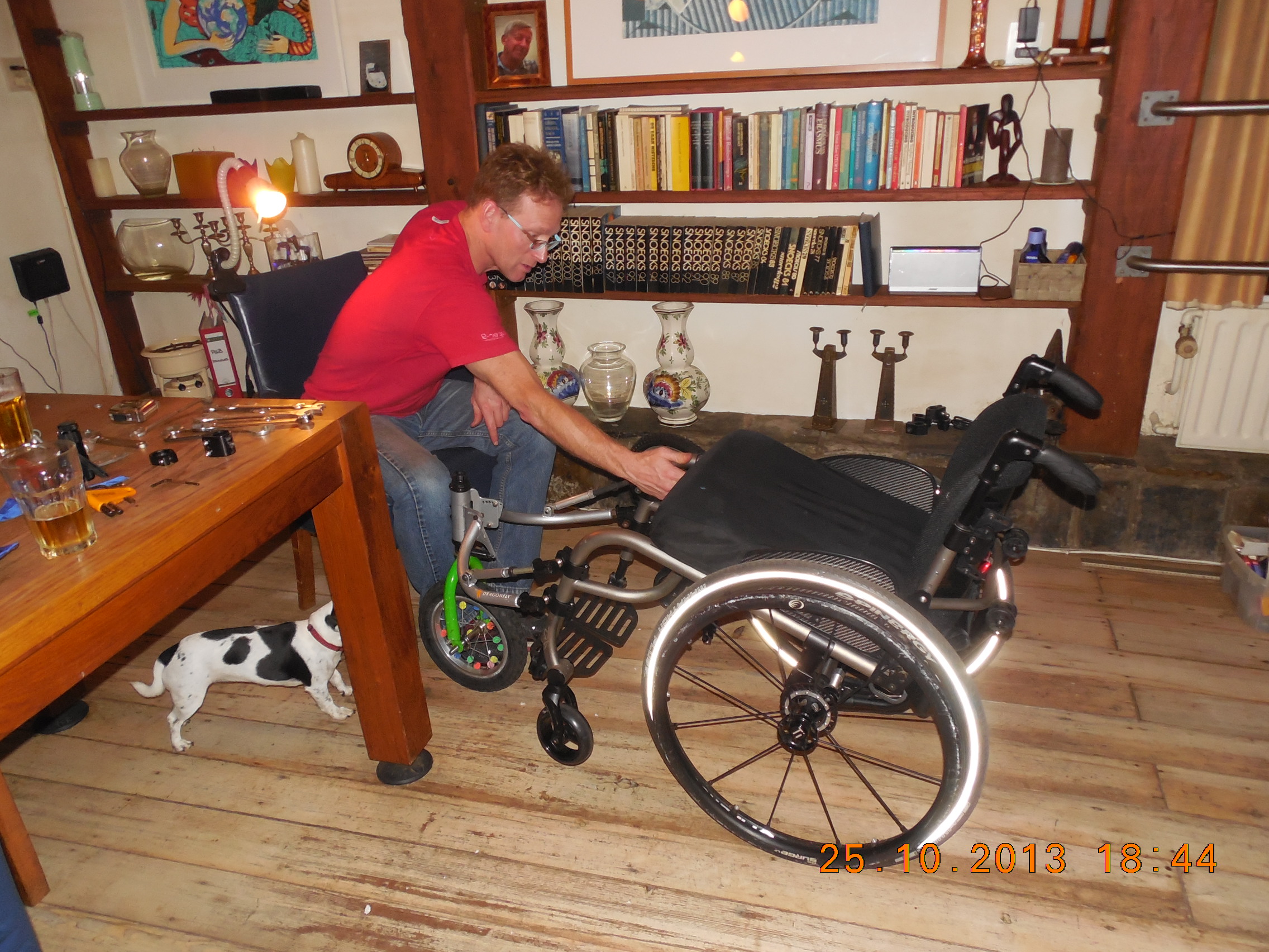
We have started to work on using the Rio Mobility attachment and fork that we bought to make an all-terrain third wheel. The project was delayed a bit because we had to change our plans because Rob broke his leg and and our travel plans changed. The parts took a rather circuitous route via my brother in Seattle and then to my sister in the Upper Peninsula of Michigan and then were checked in my luggage from Chicago to Holland.
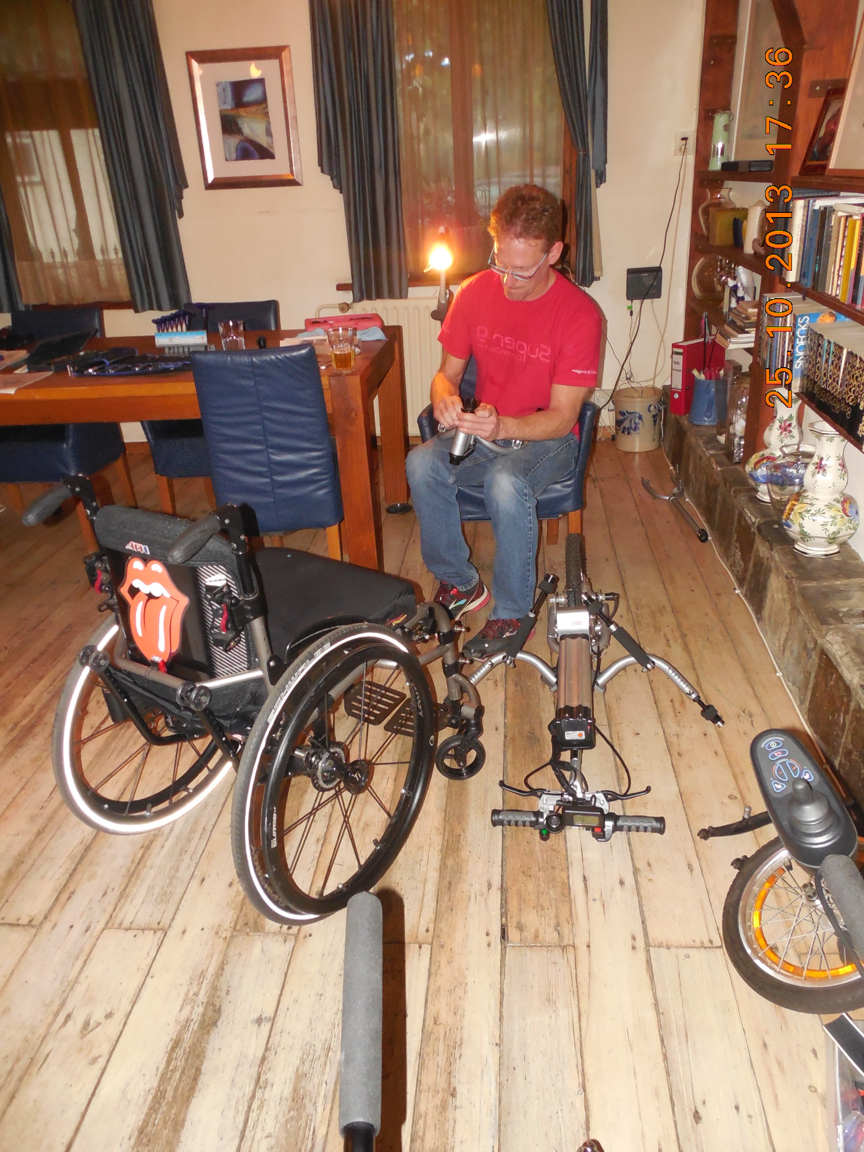
My brother Mike visited us in Holland and we got a start to this project, and also had a lot of fun doing it. We first worked to get the full Firefly attached better, which we succeeded on well. From there we played with different configurations of using the attachment and the different forks, wheels and axles. We also played with flipping the attachment upside down with the different forks, wheels and axles. What we determined was the following:
- The attachment needs to be the same as the Firefly in order have the same pawn and bracket placement with a 16″ wheel.
- The fork needs to have a negative rake so that the wheel trails properly (see the Stricker Lomo 360 and Magelan Module Tout Chemin).
Even with the above changes, we are not sure if it will work. Unless we have the identical parts we will not know. Some of our concerns are:
- Even with the Firefly fork offset ~3 cm, it does not provide enough negative rake to trail properly. Our testing with the other forks showed that the steerer needs to be vertical or at a slight negative angle along with a negative rake.
- The steerer probably needs to be from about 10° rearward from the vertical to provide the correct steering axis to swivel and handle bumps.
- Probably there also needs to be a stop mechanism so that it does not swivel completely around, or for use when going backward.
- The fork needs a negative rake of about 20° to 30° so that it rotates itself into position and trails properly. Probably this needs to be 2.5″ to 3″ ( 6.35 cm to 7.62 cm).
- The 16″ wheel will be too large while still providing enough room to swing and avoid hitting his feet, especially with a negative rake on the fork. It also made the placement of the casters much too high off the ground with the back angle tipping the chair too far back.
- If we switch to a 12″ wheel, this may be better for the chair angle not tipping back too far and foot placement with a negative rake, but may may make it difficult to achieve the same height to fit with the same pawn and bracket placement when using the full FireFly.
- We will need to work around the uneven welded Custom Rigidizer Bar on the front of the TiLite chair to get precise placement. We think this is doable, but adds more work.
Next steps for Testing Step 2
- Ellyn is going to contact TiLite to get the right connection at TiLite so that Mike can get the 3D model of the chair to help him work remotely. Status: TiLite declined.
- After talking with Mike, Ellyn is going to contact Rio Mobility about the Dragonfly attachment and fork to see if they have any input. Status: in progress.
- Mike is going to talk with some others to see what may be possible.Status: decided to wait.
-

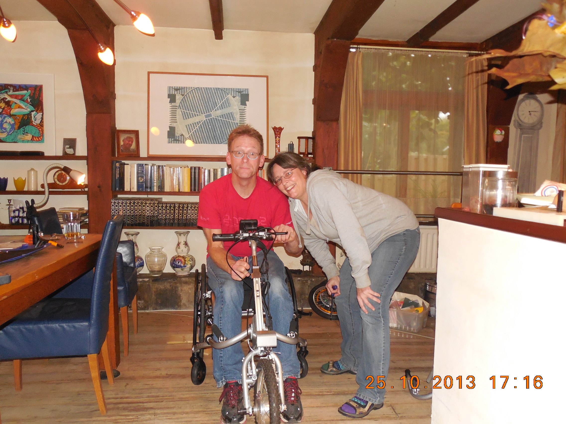
- Mikey and Rob

-
- Testing out the Firefly after adjustments
-
- An obstacle course
-
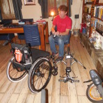
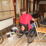
- Figuring out the third-wheel placement
-
- Lots of expirmentation
Testing Step 2 (April 2014)
I just got back to the project after a long hiatus of dealing with other stuff. I am wondering if we are not over thinking this whole project. I setup everything tonight and took a look at what the major issues are.
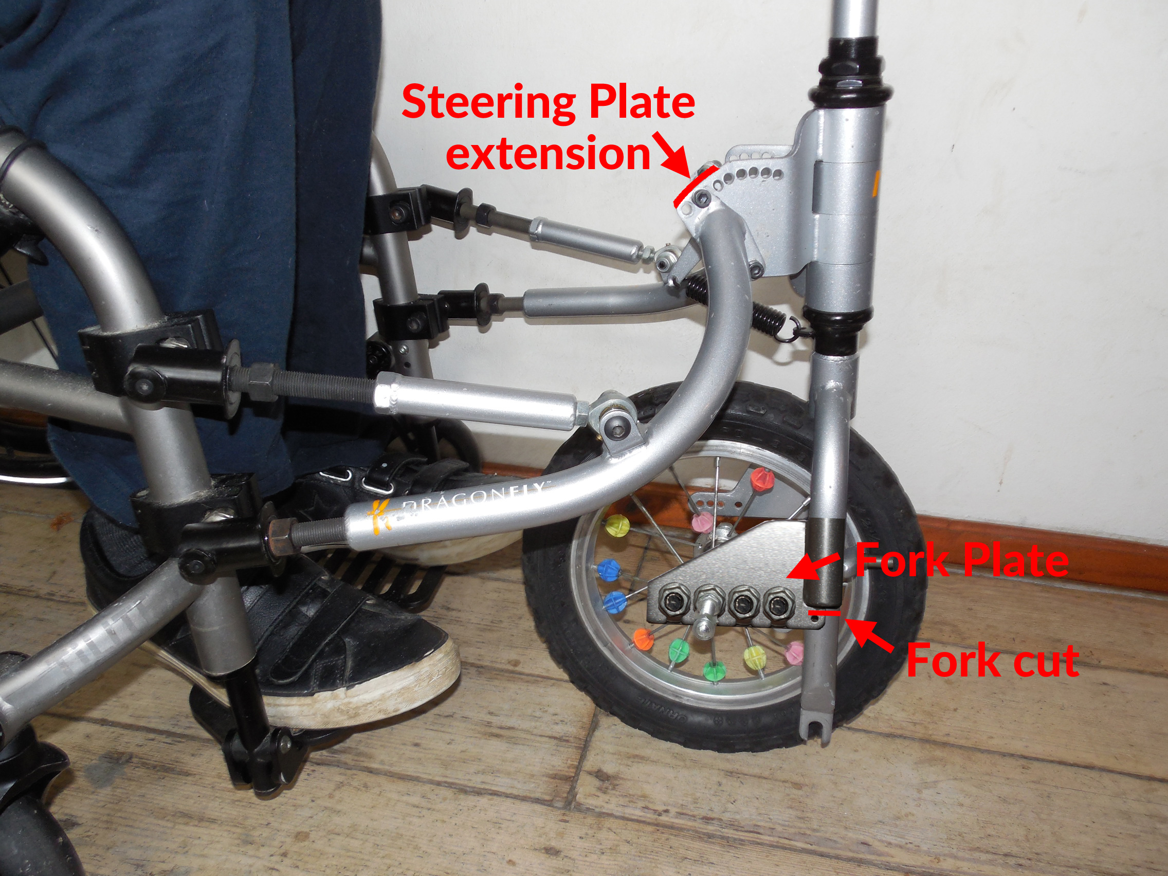
After the initial testing, I think it all comes down to getting the wheel to trail properly. I’m thinking that I could get some welder friends to extend the Steering Plates to the length we need. Probably it would be better to have the steerer more vertical so it can turn, and then either cold bend a fork or add an extension to make a negative rake.
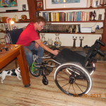
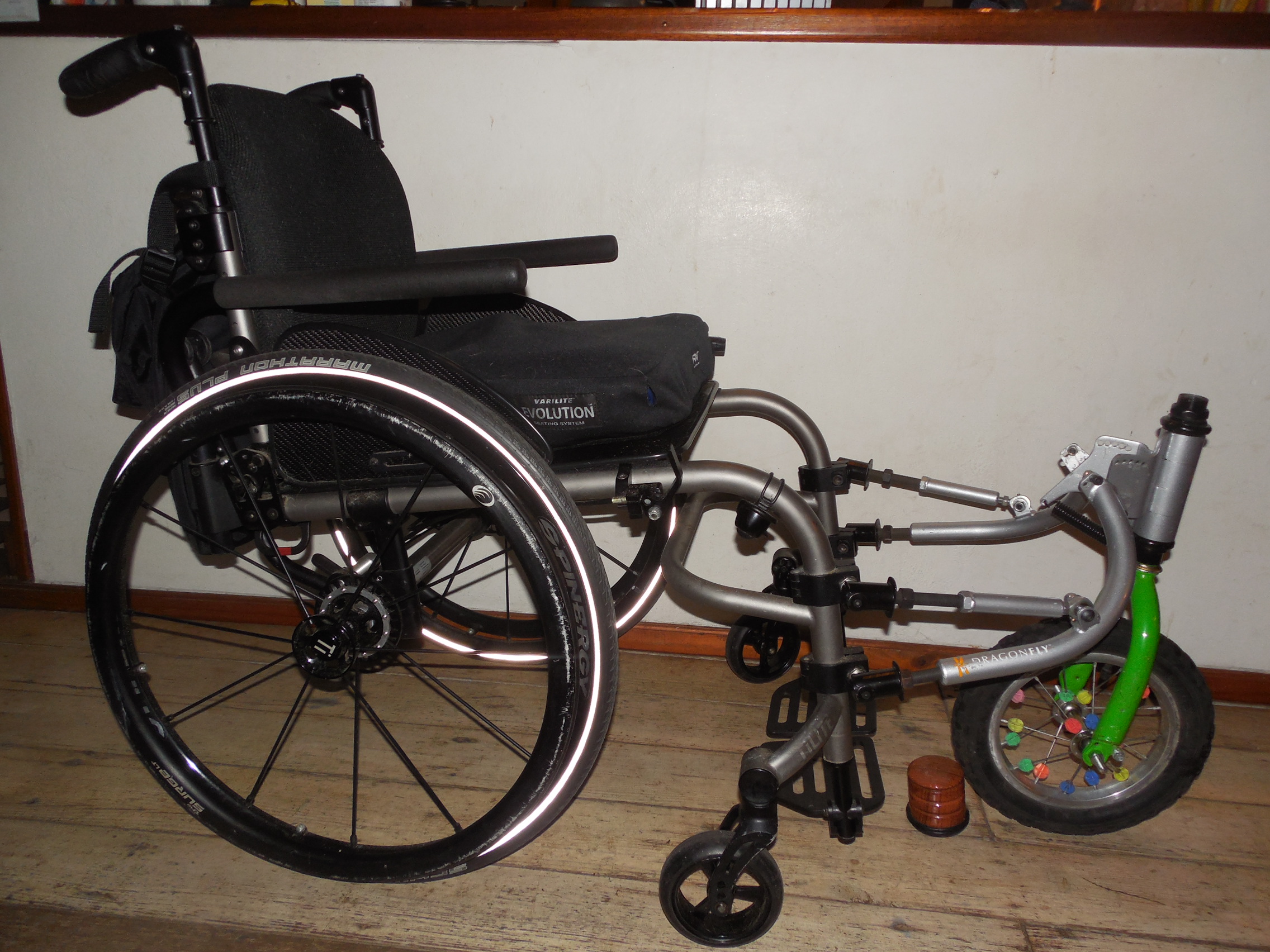
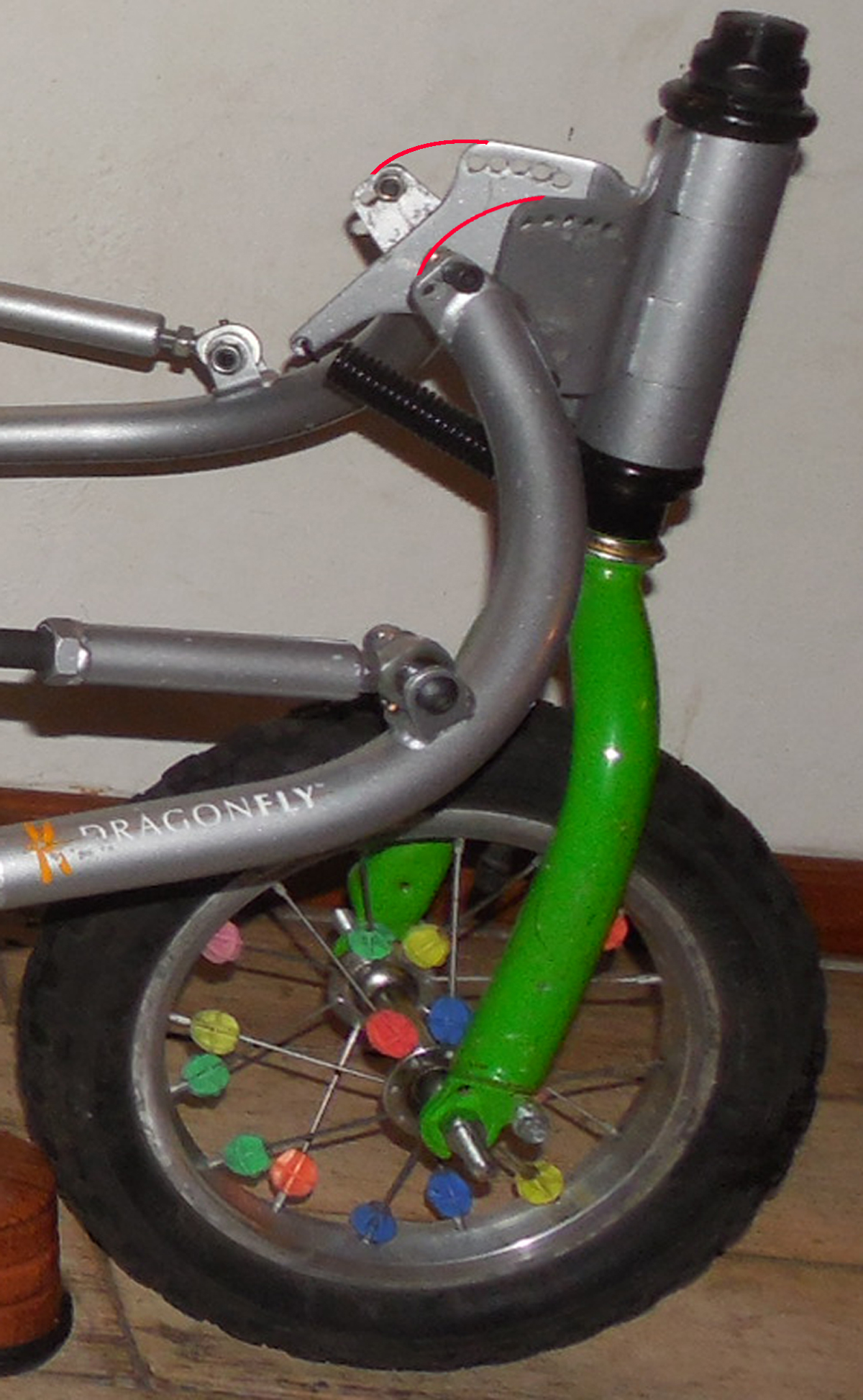
Photo’s 1
Here are some photo’s showing a 12″ wheel and a 12″ fork. I think 12″ is the maximum size wheel it could have without tipping the chair too far back and getting in the way of the attachment (and his feet). The red lines in the 2nd photo show what I mean about extending the Steering Plates. I’m going to give it a try to extend the Steering Plates with some wood, and see how it works.
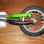
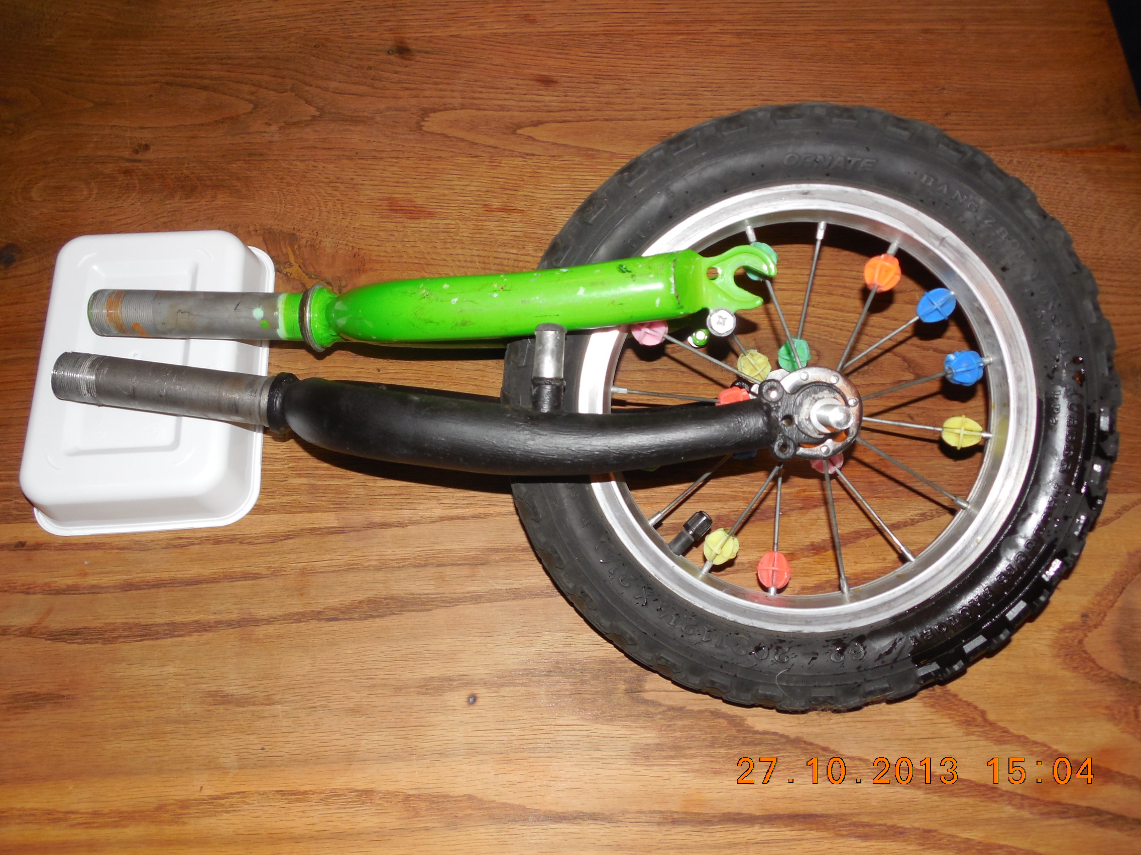
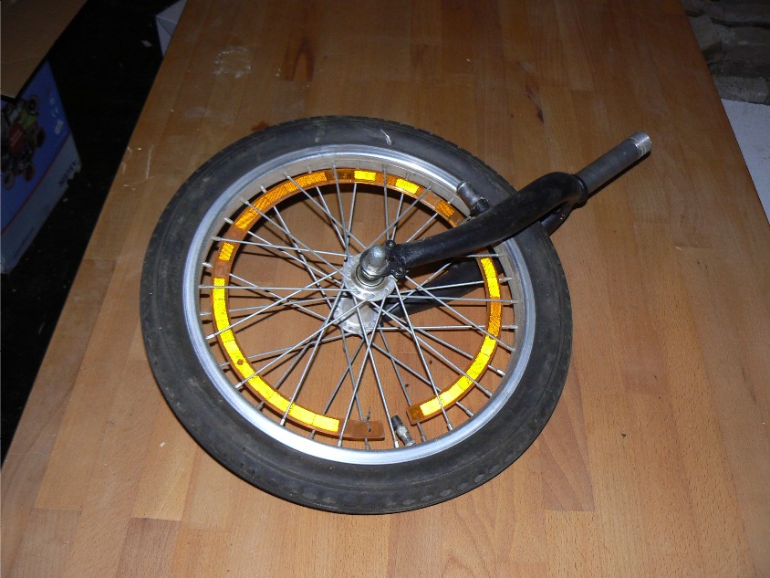
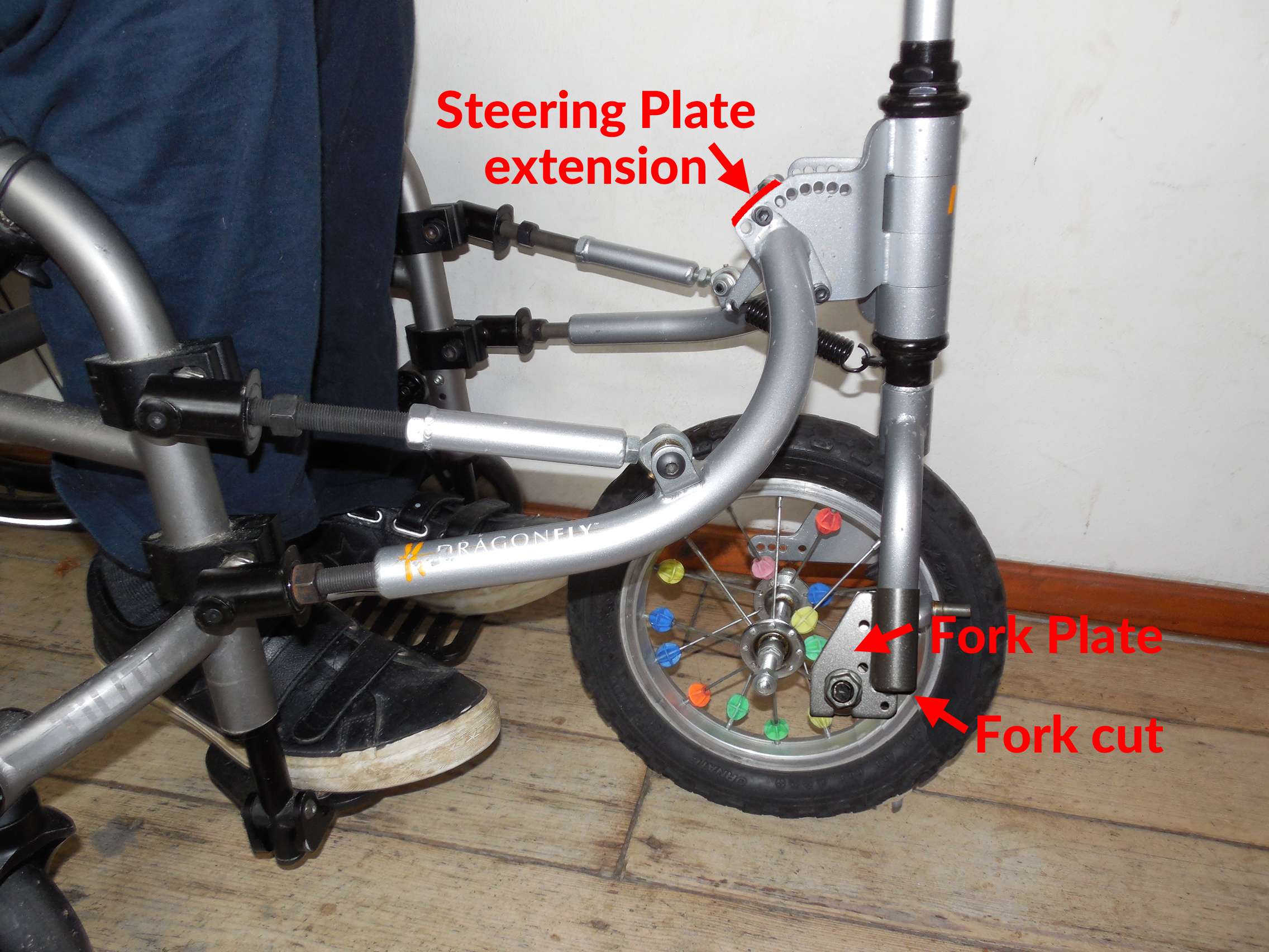
Photo’s 2
Here are some photo’s showing the 12″ wheel and the original 16″ fork shipped with the Rio Mobility attachment. The fork is more vertical, which should help it to turn better. I’ve copied an extension that is already on one side of the fork, but lowered it and used it to connect to the axel. I think it will be strong enough, because the Firefly also uses a similar fork extension to connect to one side of the axel. With having a few holes, we should be able to play with it to find the best angle. The photo’s show the wheel touching the fork under the crown, but the fork would be raised to give some space. The fork blades will also need to be cut and we will not need the dropouts.
[Note: we will also be taking the little coloured balls off the wheel]


Photo’s 3
I have made yet more photo’s. In these photo’s it is showing the fork plate extension used for the Firefly. It is looking like the same dimensions will work for this. I think going for a complete vertical on the fork is the best way to go for handling. I’ve read that a good starting point for fork offset (rake) is about 30 mm behind the contact patch, which is exactly where the Firefly axel is now, but in reverse. See this link for a quick overview about Caster angle, e.g., fork offset (rake), trail, steer angle, etc.
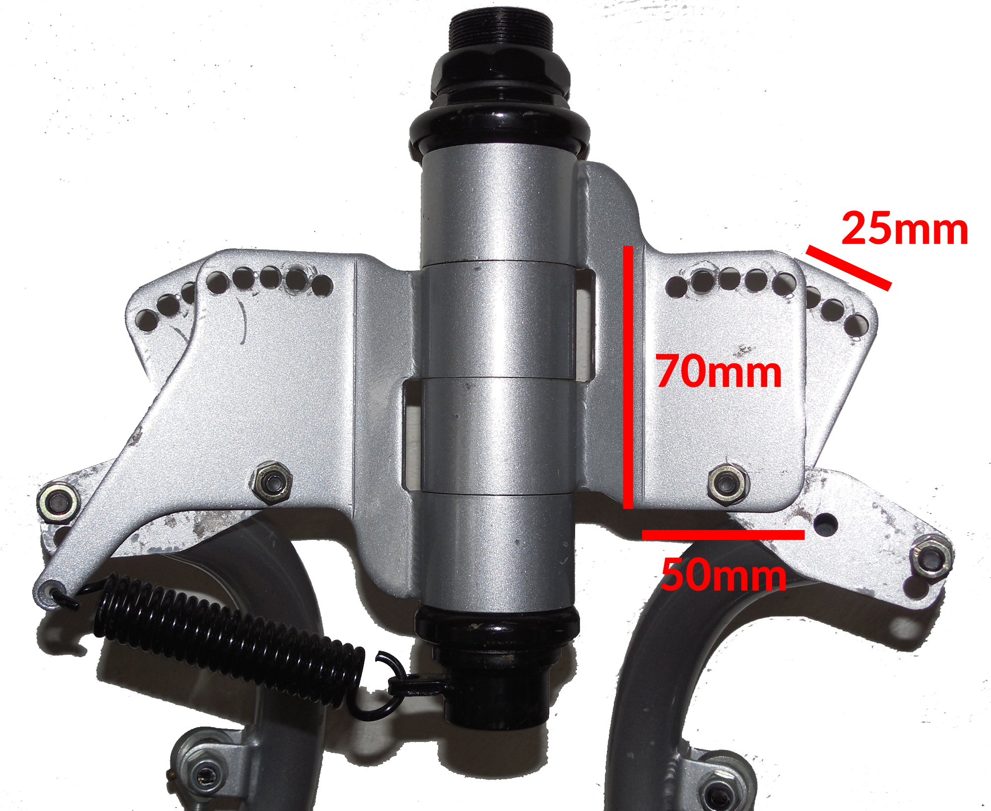
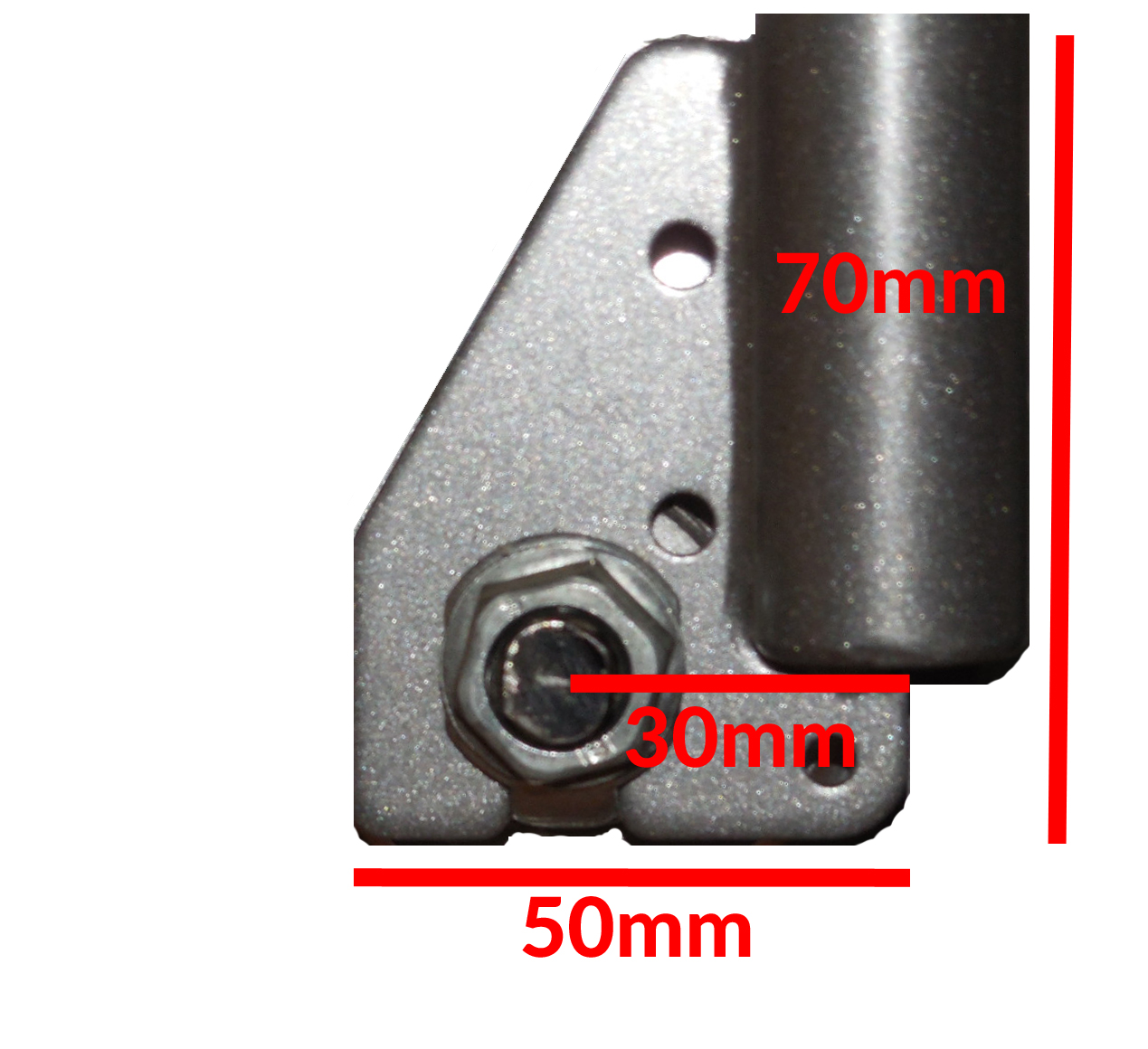
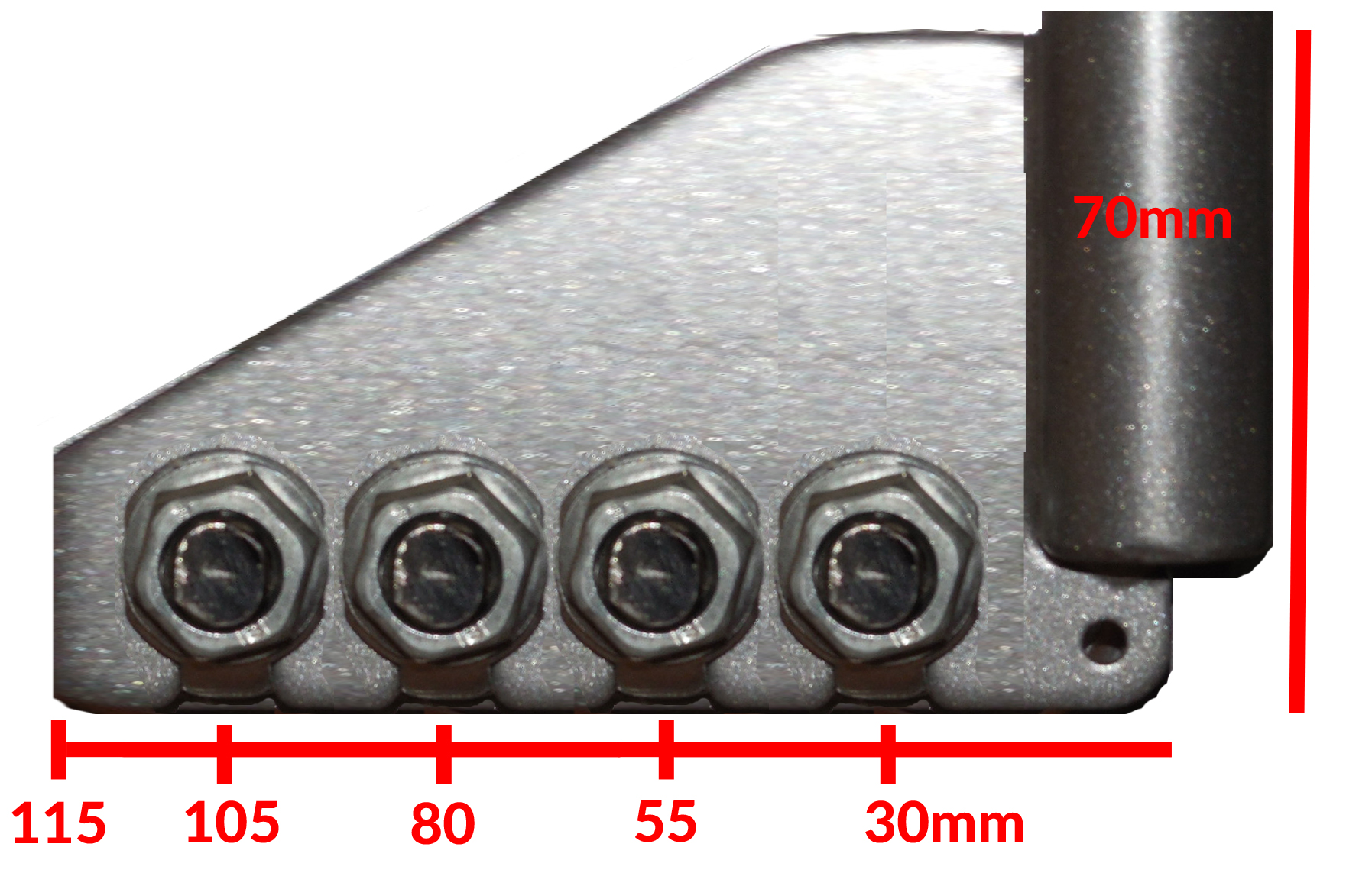
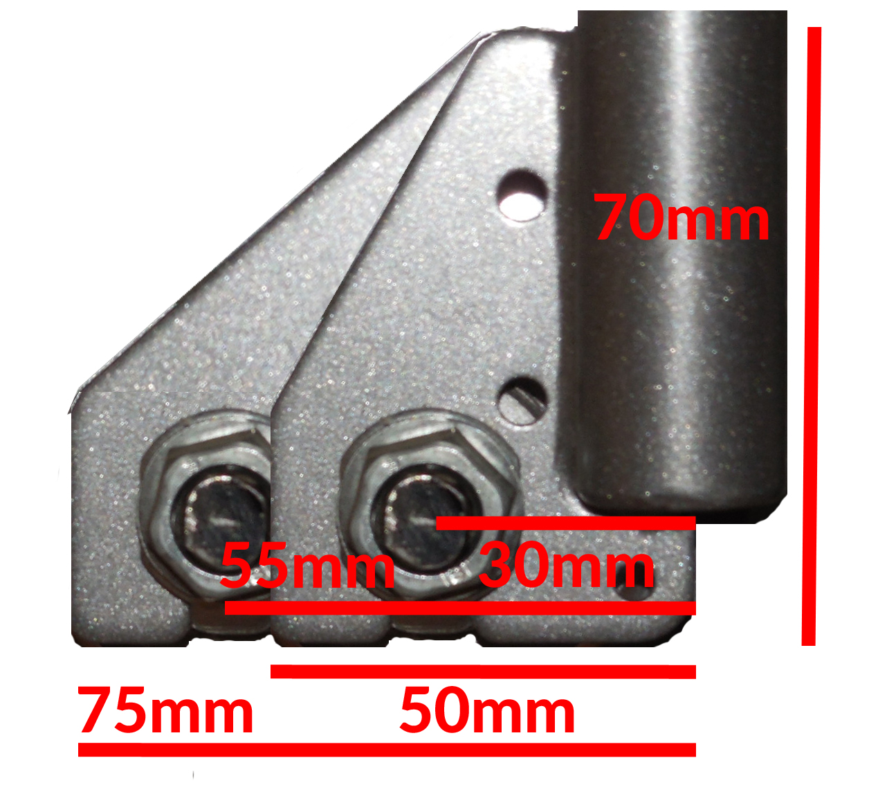
Photo’s 4
I am getting input from others that we may need an even more excessive fork offset (rake). I had taken into account that we might want a bit more, and made a mock-up with a total of 55 mm. Now I am not sure if even that will be enough, as it was mentioned that they needed 140 mm for a good trail. I was given a good suggestion to experiment using adjustable clampable plates. This picture only shows 2 dropouts, but maybe we should consider doubling it to 4 until we know what works.
Photo’s 5
I got some more input from RioMobility. They agreed that the steering axis should be close to vertical and think that we will need more than 3cm trail — at least double that. I think I’ll talk to our welder friend about making a longer plate that we clamp on the inside of the fork and experiment with different dropout positions. I only know the very basics of welding, but we are lucky to have a few good welder friends. At least having the steering axis vertical should make for less variables while testing everything. I think that if we would have started there it would have saved a lot of time, but then again, ya live and learn.
I measured the other third wheels that are a similar concept, and all of them have from 25 to 29 degree of trail behind the vertical axis. I have made yet more photo’s to give more options for placement.